
In this note, a demo of a shell-reinforced bending soft pneumatic actuator (SPA) is presented. From the demo, we can have a general idea of the procedures of implicit dynamic analysis using Abaqus.
References:
Step 1: Create Actuator Geometry (Parts)
- A single air chamber is modeled for providing enhanced mechanical reliability of the actuator by eliminating stress concentrations at narrow passage walls.
- The cross-section of the air chamber is circular.
- The bending actuator achieves bending motion due to a thin un-stretchable layer attached at the bottom of the structure.
- Due to the symmetry of the structure, only half the portion of the entire actuator is created and modeled.
Geometric Parameter:
The following geometry is generated in Abaqus CAE for a bending actuator with an outer diameter of 4 mm, wall thickness of 2 mm and total length of 40 mm. The number of cuts on shell surface is 7, at a cut spacing of 1 mm.
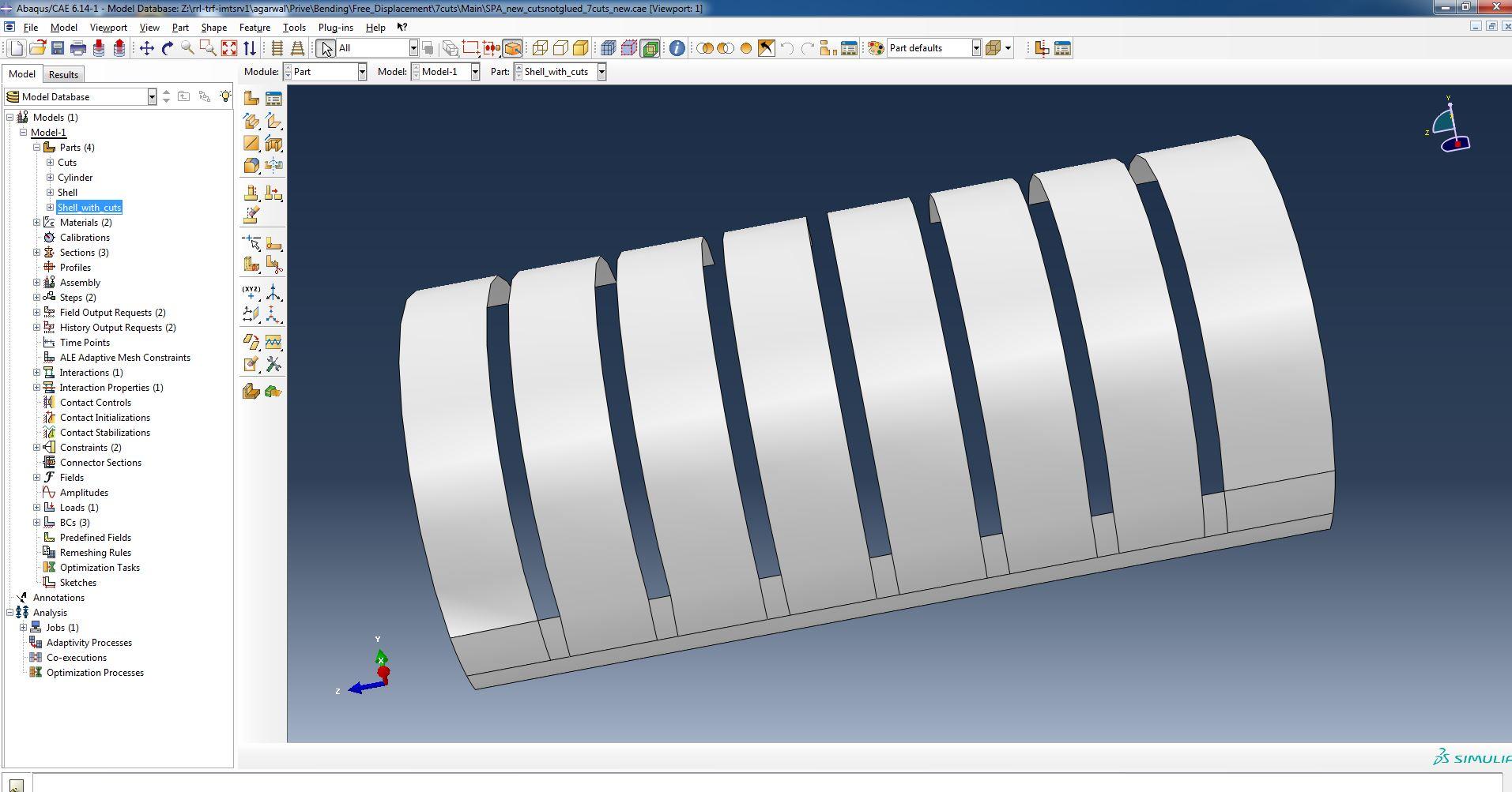 Shell part of the linear actuator (4 parts are created, namely Cuts, Cylinder, Shell and Shell with Cuts)
Step 2: Define Properties
Material Constitutive Model
In the demo, the chamber is made in Exoflex-30 material while the thin un-stretchable shell layer is made of a plastic material such as PET.
The material Ecoflex-30 is modeled using a hyperelastic model. A 3-term Ogden model is used for Ecoflex-30 in this example, with the following coefficients:
mu1 = 0.001887; alpha1 = -3.848; mu2 = 0.02225; alpha2 = 0.663; mu3= 0.003574; alpha 3 = 4.225; D1 = 2.93; D2 = 0; D3 = 0
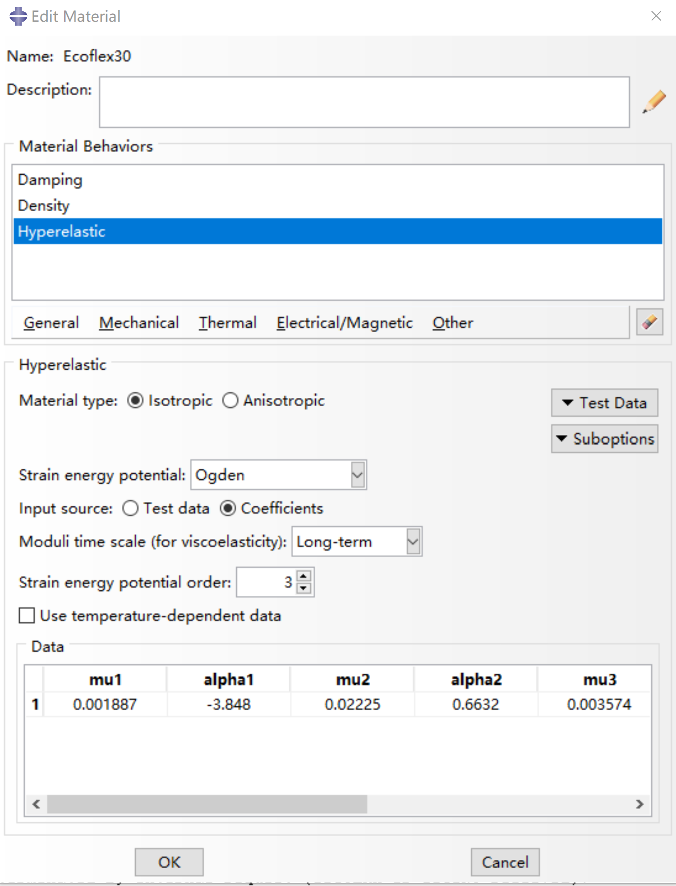 Hyperelastic property of Ecoflex-30
The shell is modeled using a linear elastic model (due to stresses in shell not exceeding elastic range). The elastic property can be defined by Young’s modulus and Poisson’s ratio:
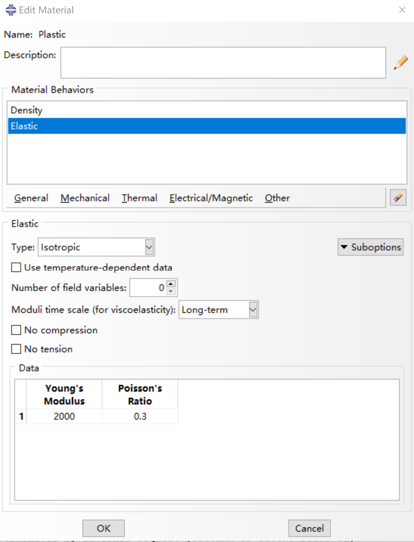 Linear elastic property of plastic
Sections and Material Assignment
Create the sections of the parts of the actuator (Cylinder and Shell), using the default settings.
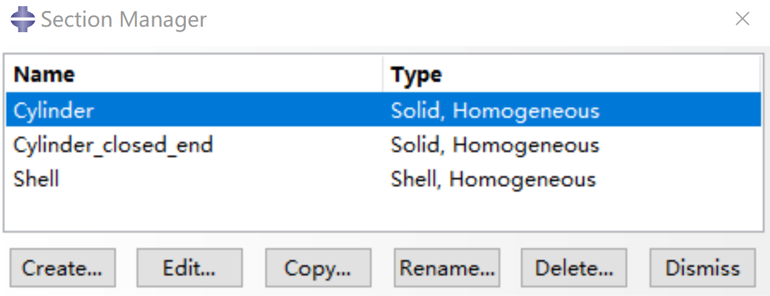 Sections of the model
Assign the part (section) Cylinder with the material Ecoflex-30 and Shell with plastic.
Material can only be assigned to a part when a section is defined.
Step 3: Define Assembly
- Create Instances to add parts to the assembly.
- We can further create some Sets and Surfaces, such as the inner of the tube (Tube_Inner).
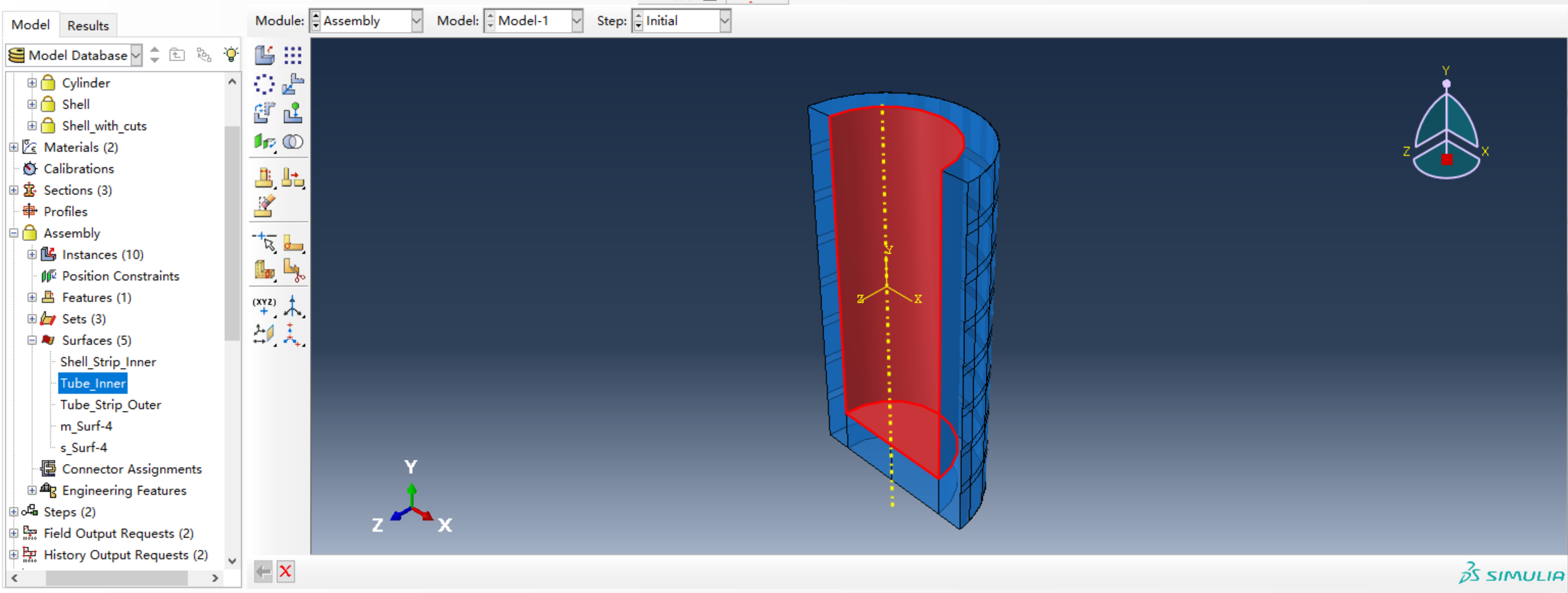 Create inner surface of the tube
Step 4: Define Steps
Define Implicit Dynamic Step
- Time period: 200
- Nlgeom: On
Nlgeom must be turned on for large deformation!
- Application: Quasi-static
- Incrementation Type: Automatic
- Maximum number of increments: 10000
- Increment size: Initial 15, Minimum 1E-6, Maximum 15
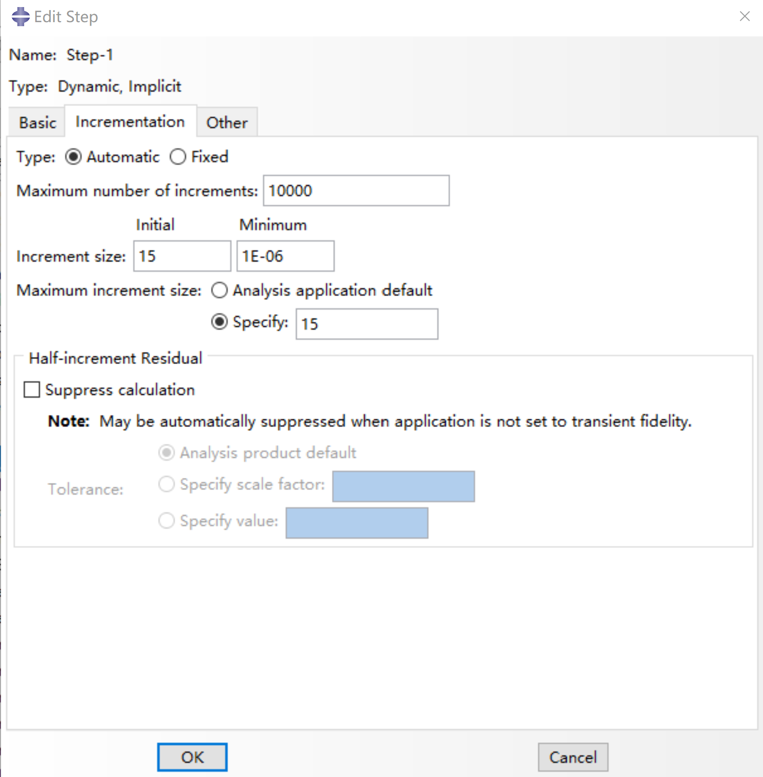 Incrementation of the step defined
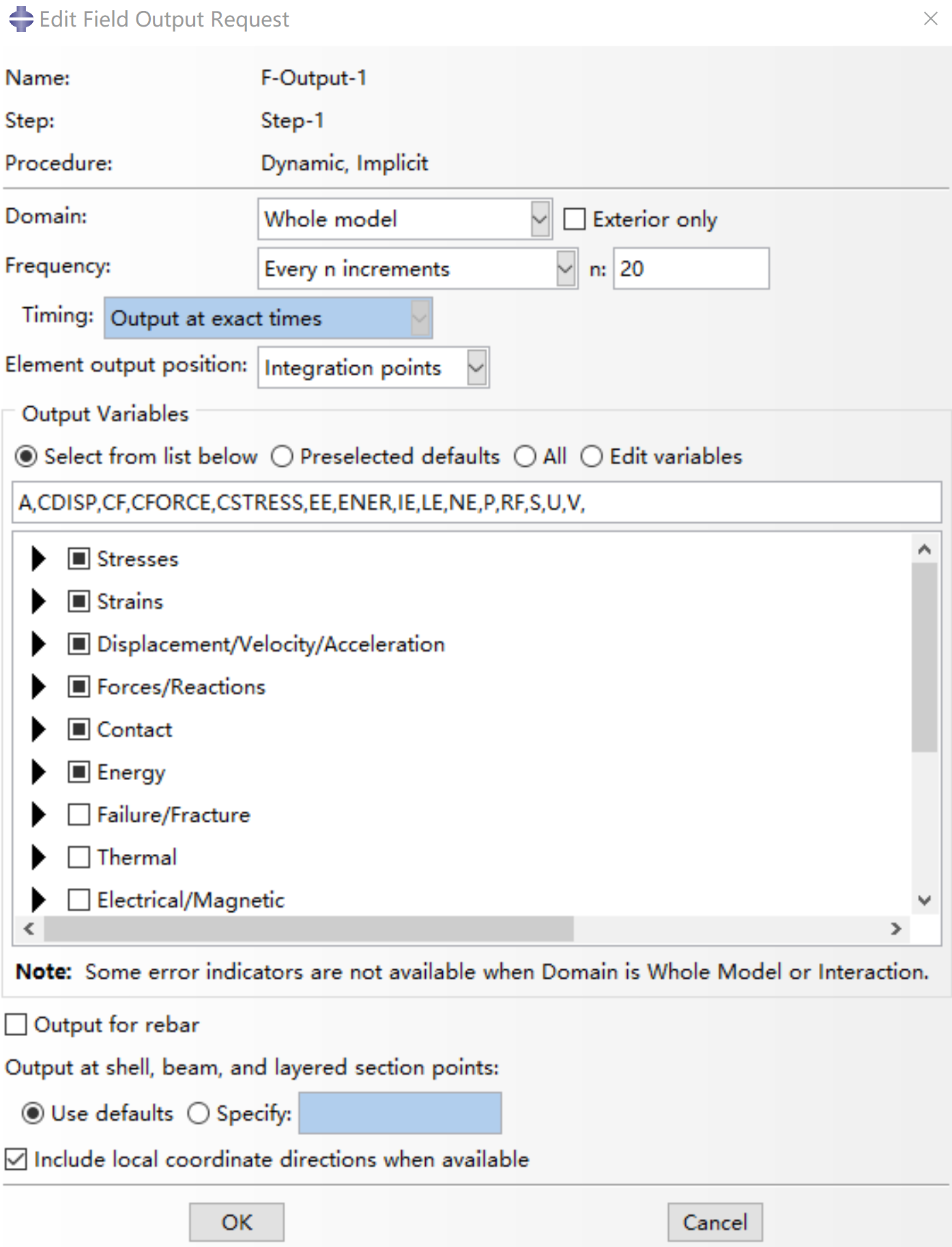
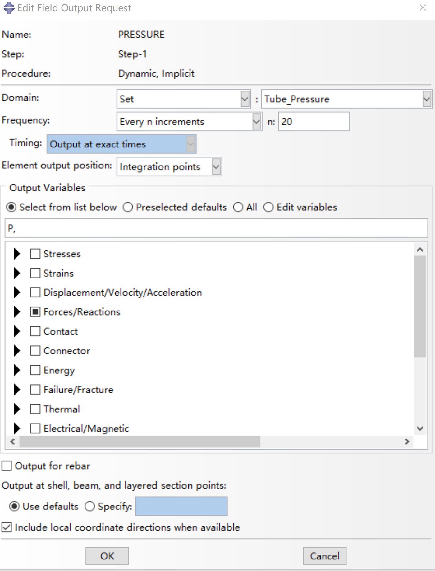
Define Field Output
- F-Output-1
- Pressure
Define History Output
- H-Output-1
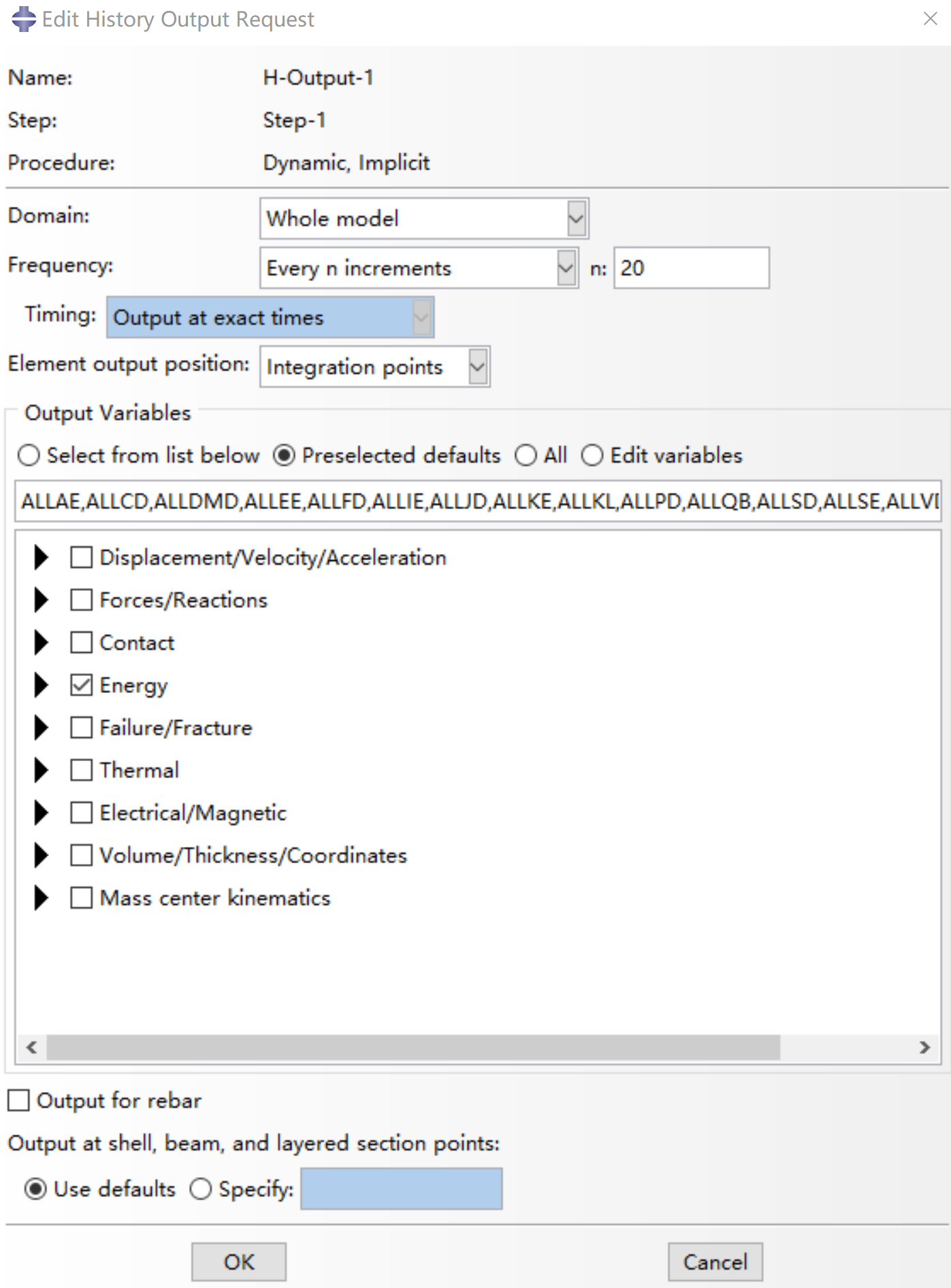 Choose all items in ‘Energy’
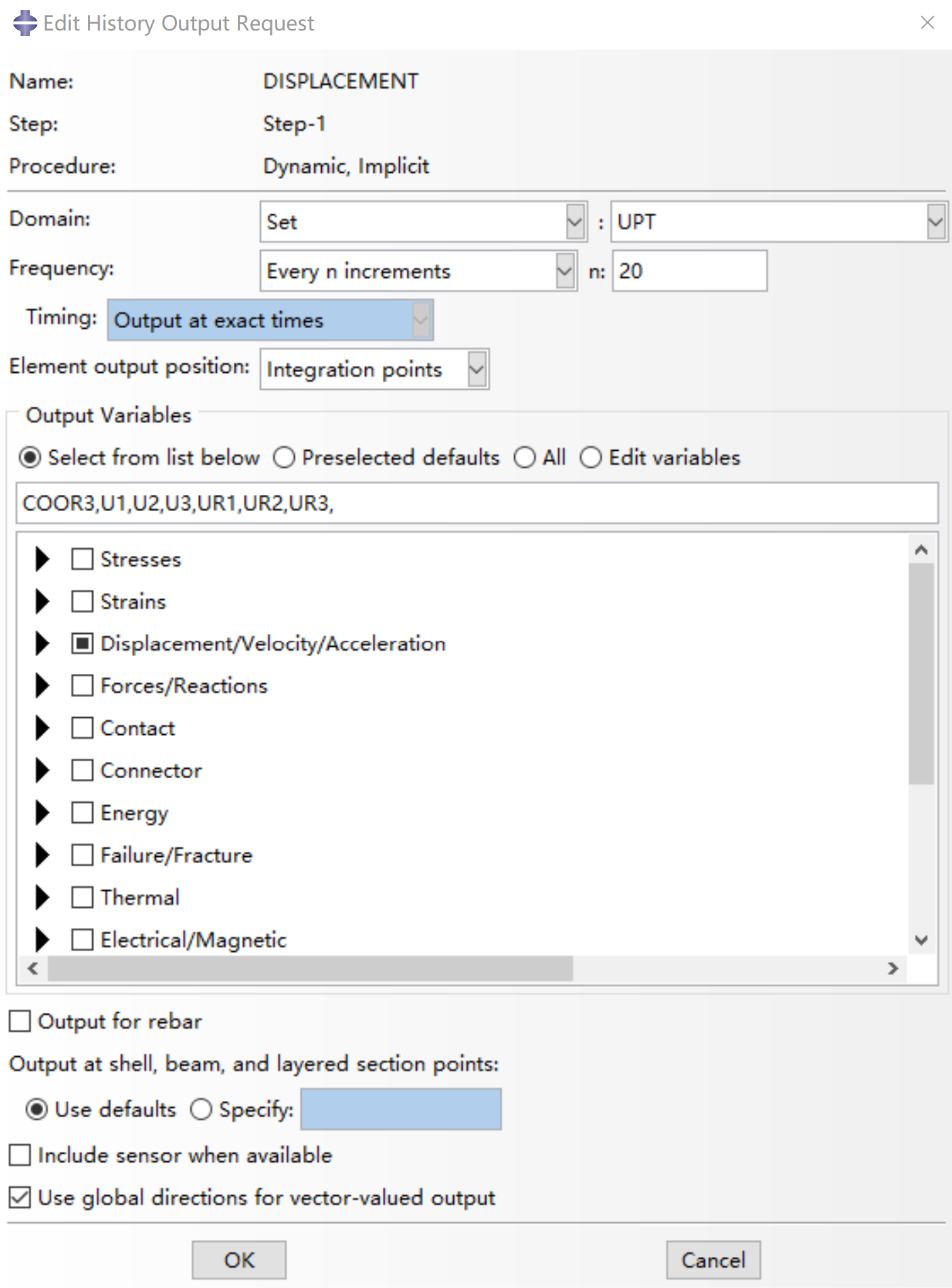
- Displacement
Step 5: Meshing
In this case, due to the hyperelastic behavior of the material used to create the actuator core, standard linear 3-D stress elements are used with hybrid formulation and reduced integration.
For the shell structure, standard linear shell elements with reduced integration are used. The following image shows the mesh generated for the shell, as an example.
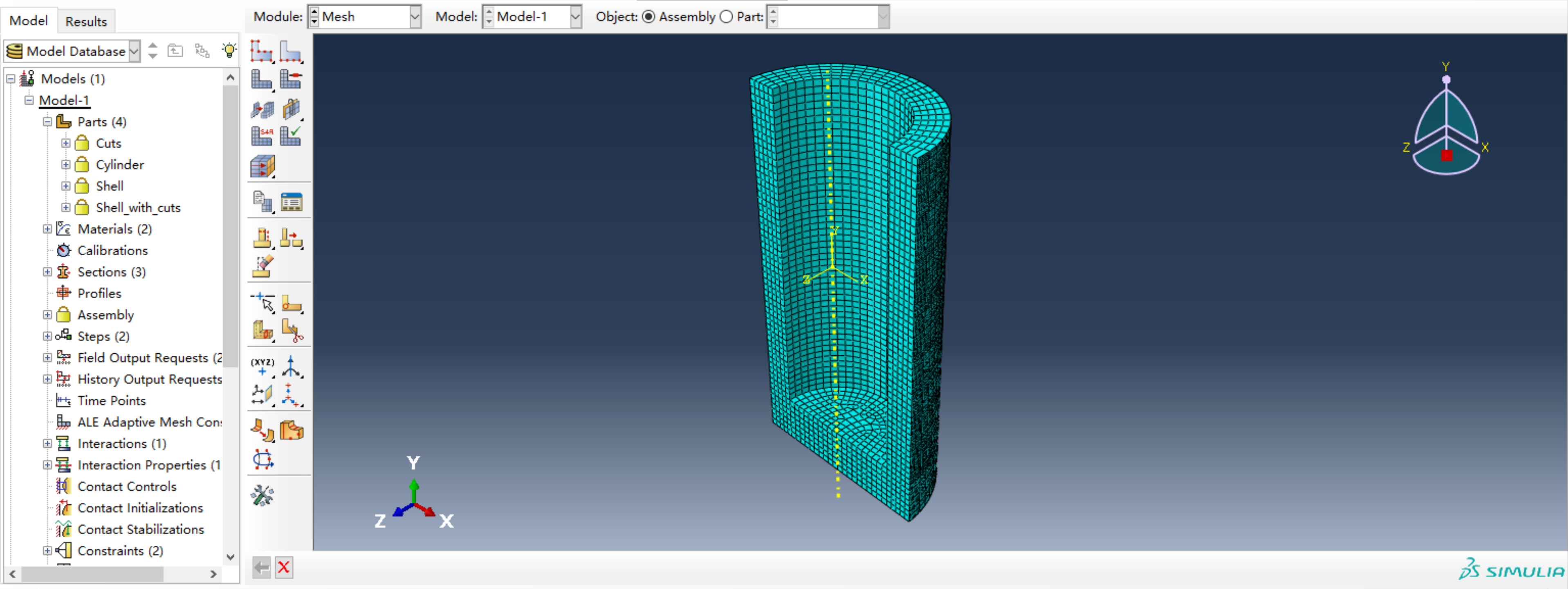 Meshing result
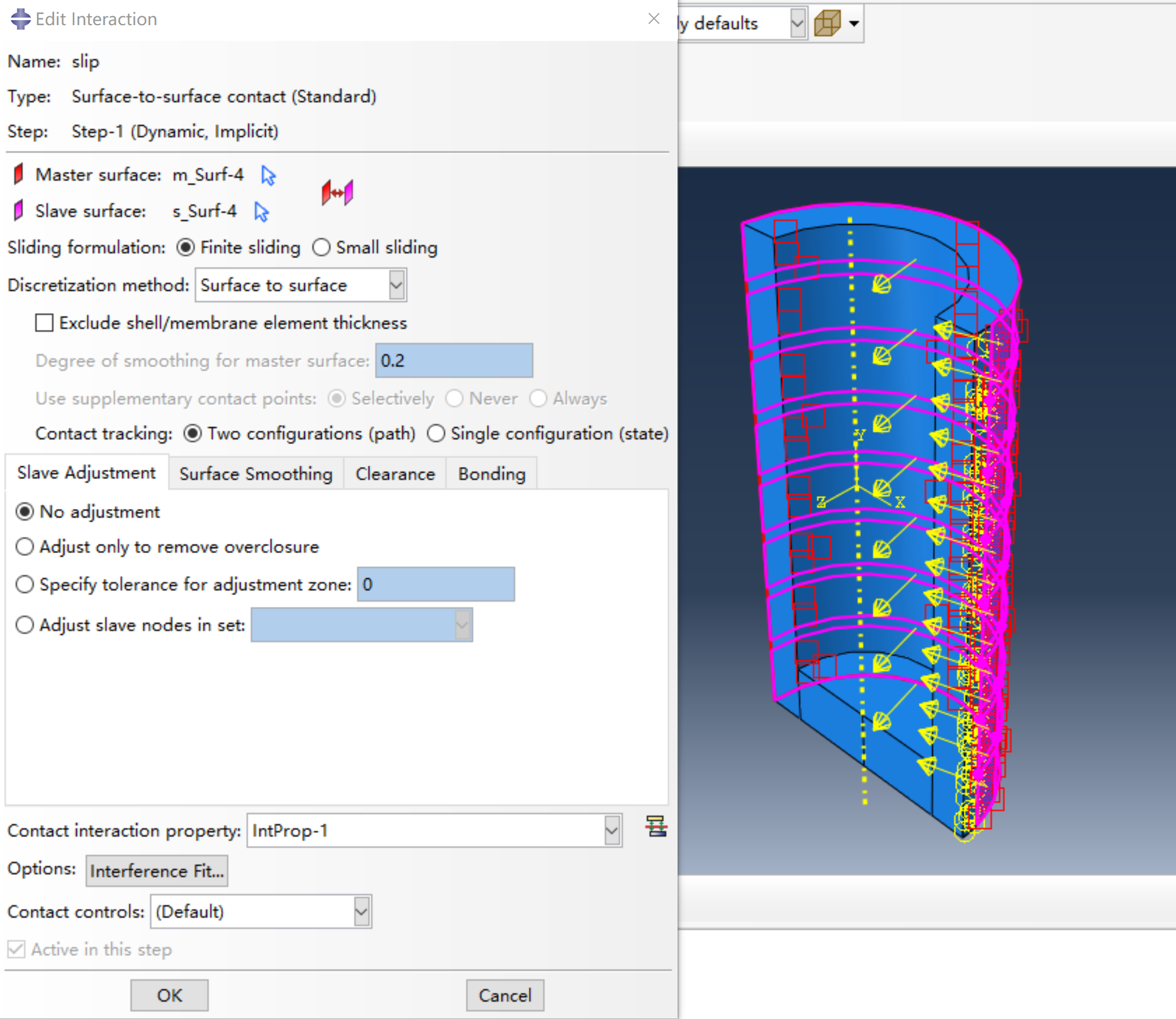
Step 6: Define Interactions
To achieve bending motion profile, a thin strip portion at the bottom of the shell is attached to the core surface using an adhesive. The shell is permitted to slide over the surface of the actuator and guide its trajectory in the remaining portions. To implement this condition in Abaqus, a tie constraint is imposed at the thin unstretchable portion while a contact property is defined to include finite sliding in tangential orientation with a specified coefficient of friction in the remaining portions.
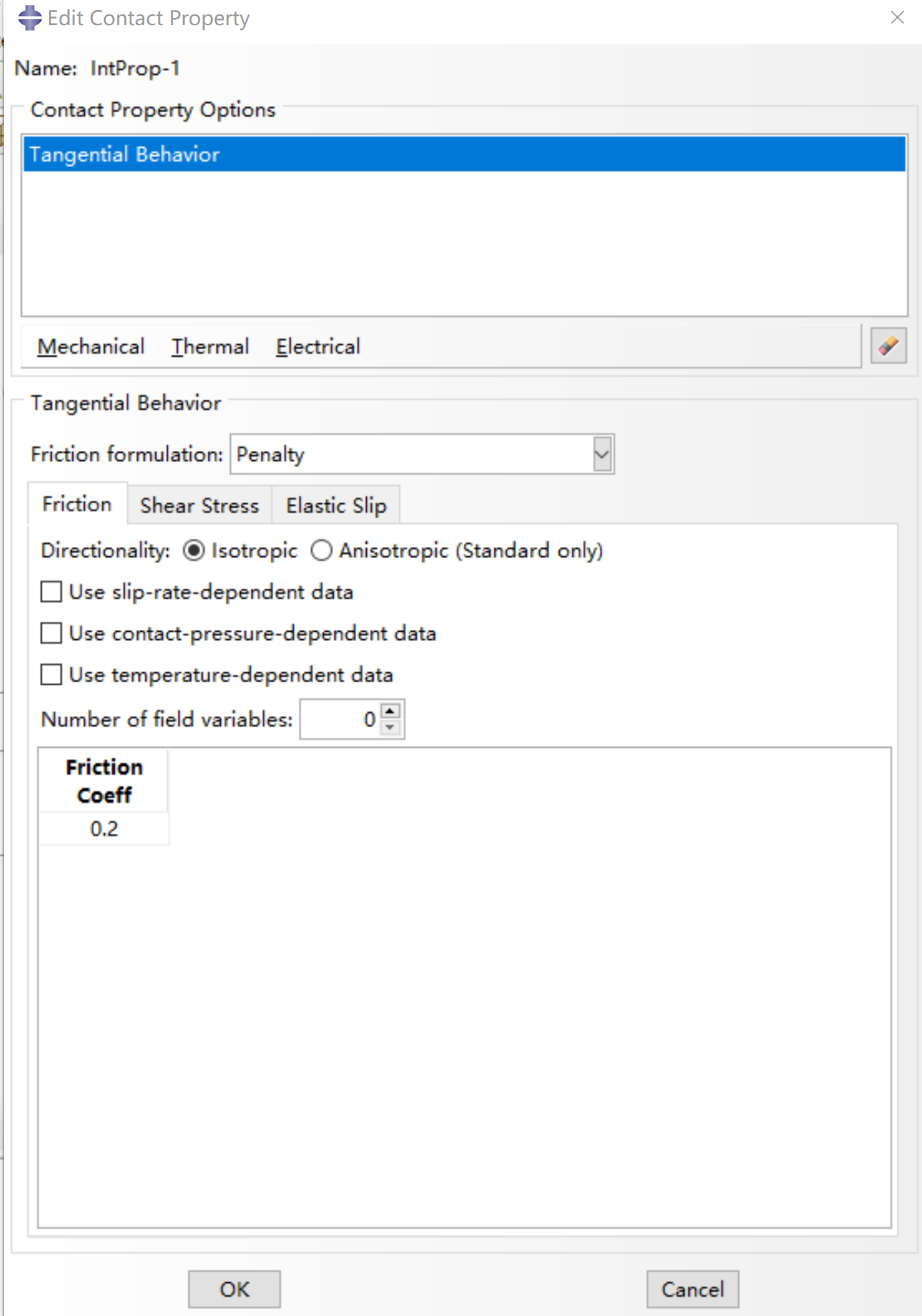
First define the interaction property Tangential Behavior:
- Friction formulation: Penalty
- Friction Coeff.: 0.2
Then define the sliding interaction between the cylinder and the shell.
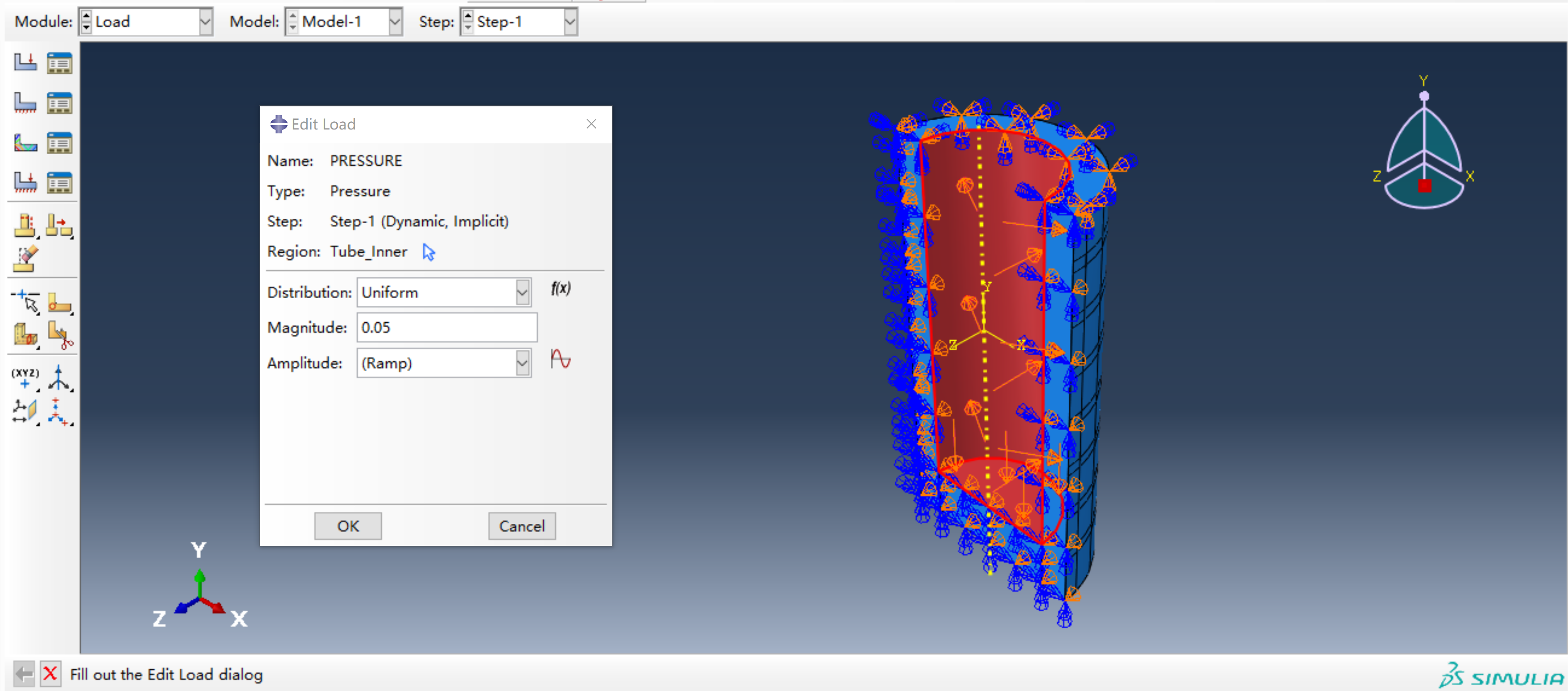
Step 7: Define Pressure Loads
An input pressure of 50 kPa was specified on the chamber walls.
Step 8: Define Boundary Conditions (BCs)
- Half Symmetry
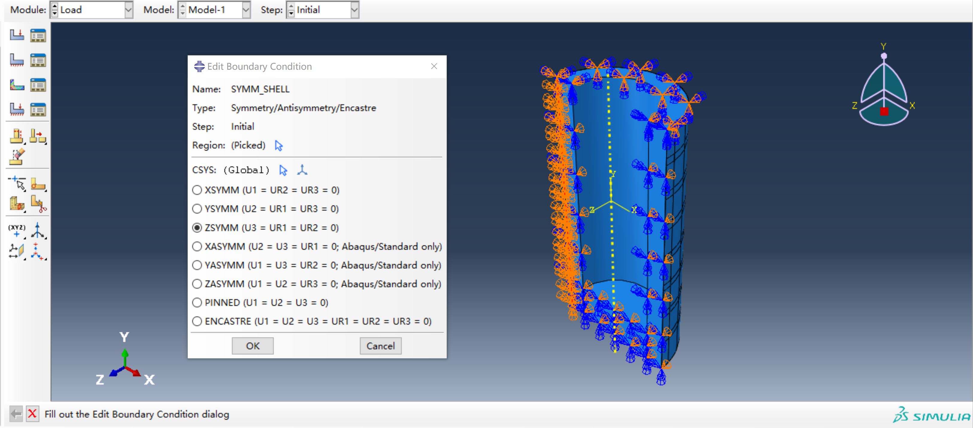 Half symmetry of shell
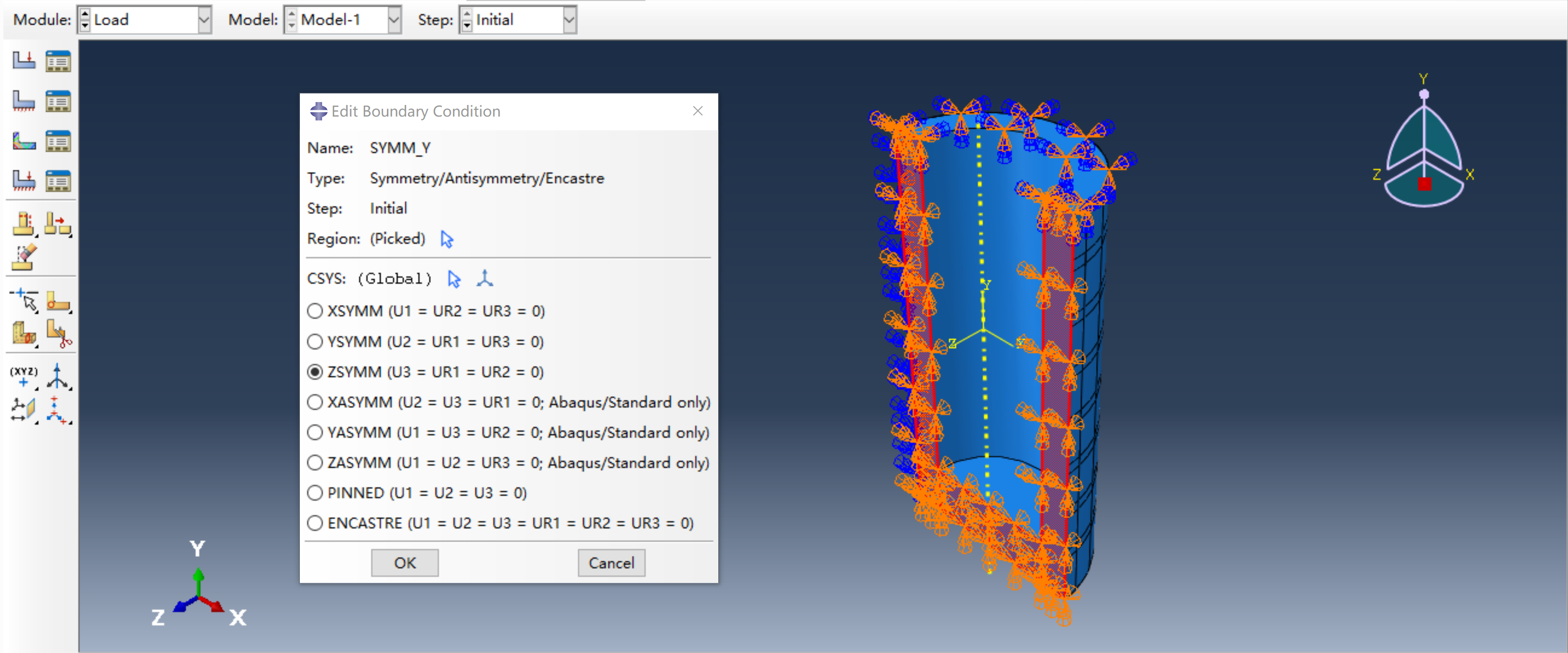 Half symmetry of cylinder
- No translation or rotation for the inlet portion
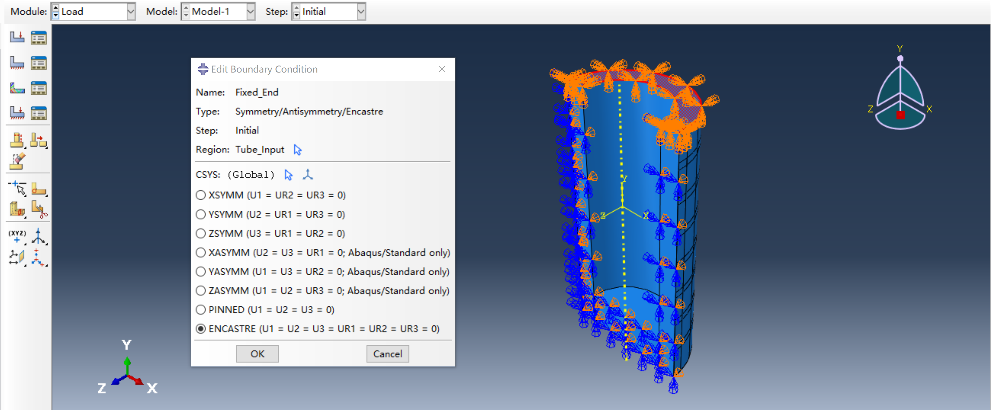 Fixed end
Step 9: Create Job
Create a job using the default settings and Submit!
Step 10: Post-processing
A variety of analysis can be performed.
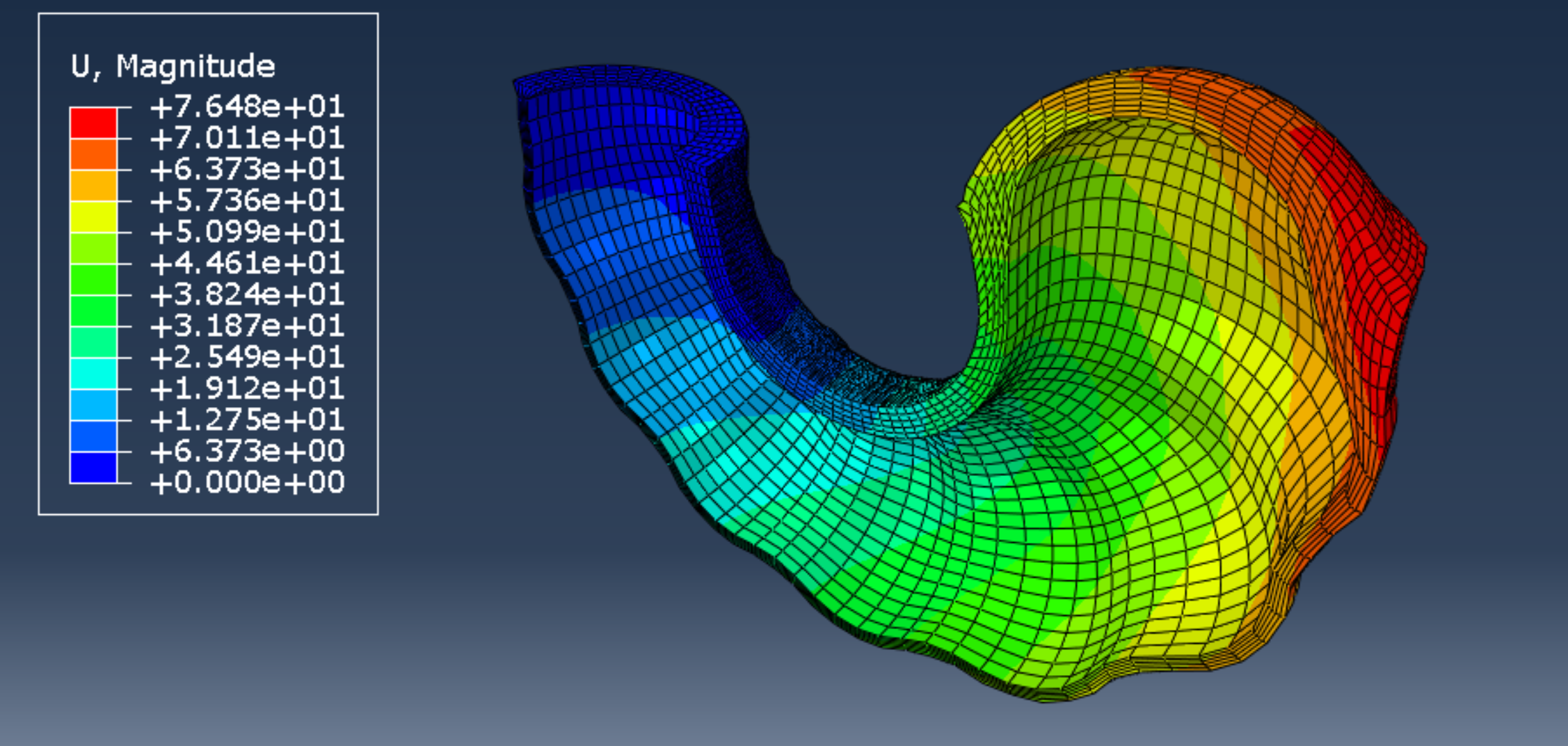 Abaqus ODB result plots for linear extension motion generated are shown for the free displacement condition
Comments powered by Disqus.