
This is a note on the article Design, kinematics, and control of a soft spatial fluidic elastomer manipulator. This paper presents a robotic manipulation system capable of autonomously positioning a multi-segment soft fluidic elastomer robot in three dimensions.
- A new spatial manipulator morphology that is modular in design and well suited for automation.
- Multi-step casting process to build manipulators 3D.
- A static model to understand how a single segment deforms.
- Model of the multi-segment kinematics of the soft manipulator
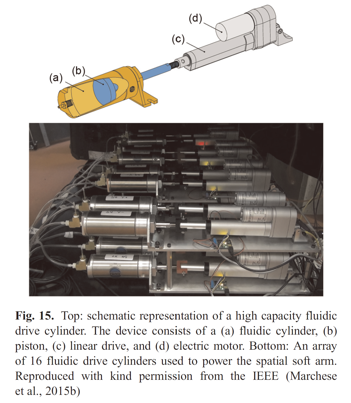
- Power: high capacity fluidic drive cylinders.
- A real-time closed-loop control algorithm that generates realizable curvature trajectories, measures the arms current state using localized segment endpoints, and leverages a cascaded control strategy.
Introduction
Several advantages of the fluidic elastomer manipulator’s continuum kinematics and soft material composition:
- The manipulator’s soft segments deform according to constant curvature.
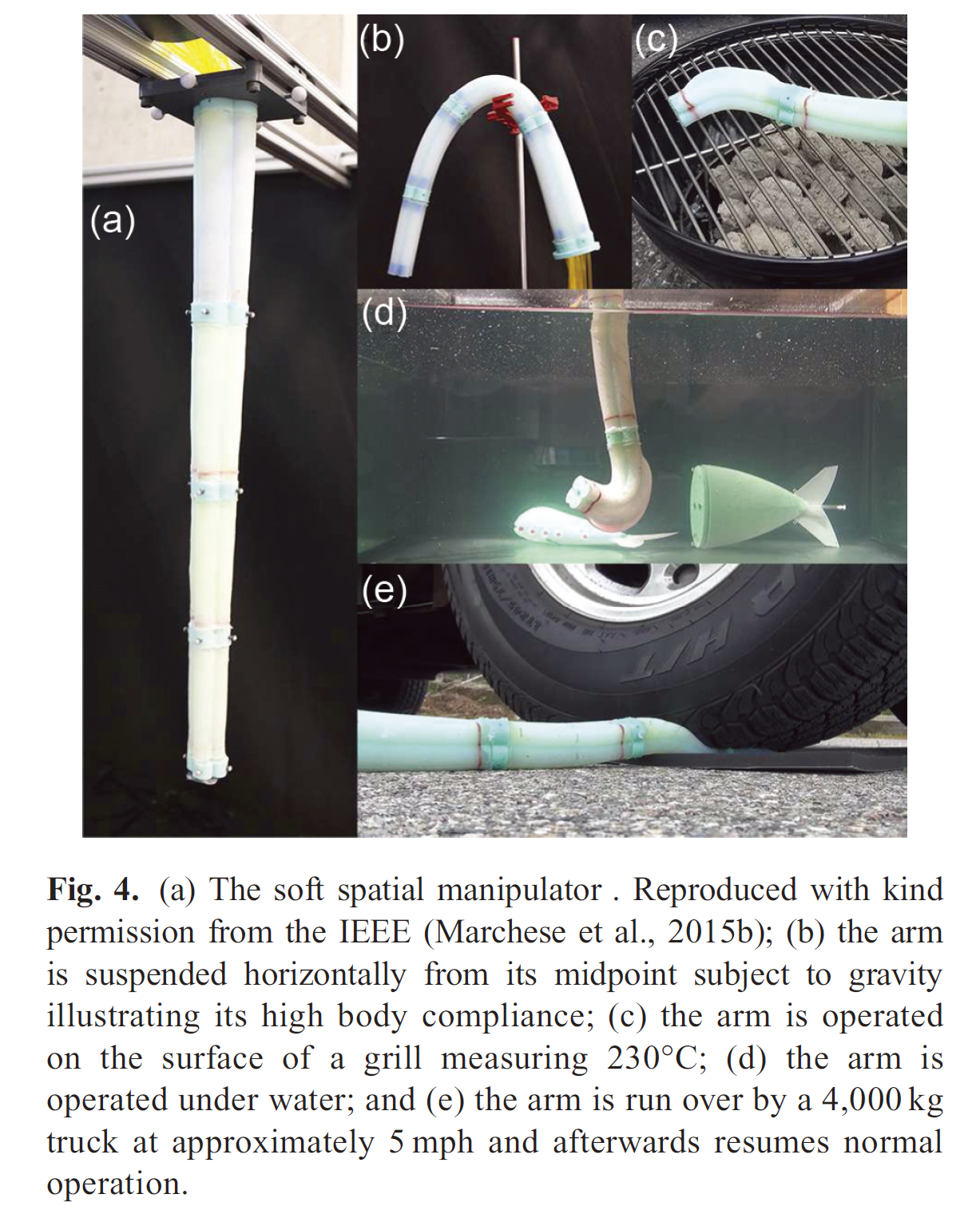
- The kinematics and extreme compliance of such a soft manipulator enable it to fit within and advance through confined environments.
- A high degree of dexterity
A review of soft manipulator designs
Continuously deformable backbones
Soft continuum manipulators. Two primary morphologies:
- Tendon driven arms
- Fluidic elastomer actuators. Advantages:
- can be lightweight making for easy integration into distal locations of the body;
- conforms to the time varying shape of the manipulator;
- does not require rigid components to implement.
A review of soft manipulator kinematics
Robot-independent model
Piece-wise constant curvature (PCC) model
Assumption: each body segment of a multi-segment arm is assumed to deform with constant curvature.
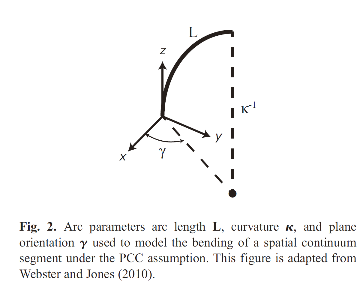
Forward kinematic transformation for a single continuum segment:
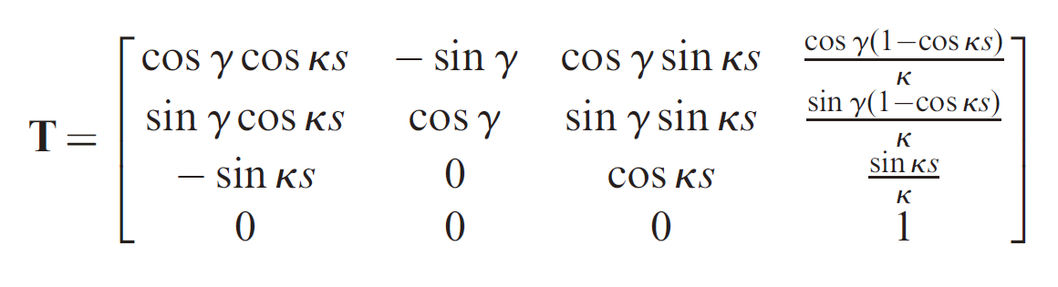
where
Obvious limitation: Not all continuum robots deform according to segmented constant curvature. A common exception is when a continuum body segment assumes a spiral, i.e. curvature increases from the segment’s base to tip.
Robot-dependent model
Mapping: actuation space
System Overview
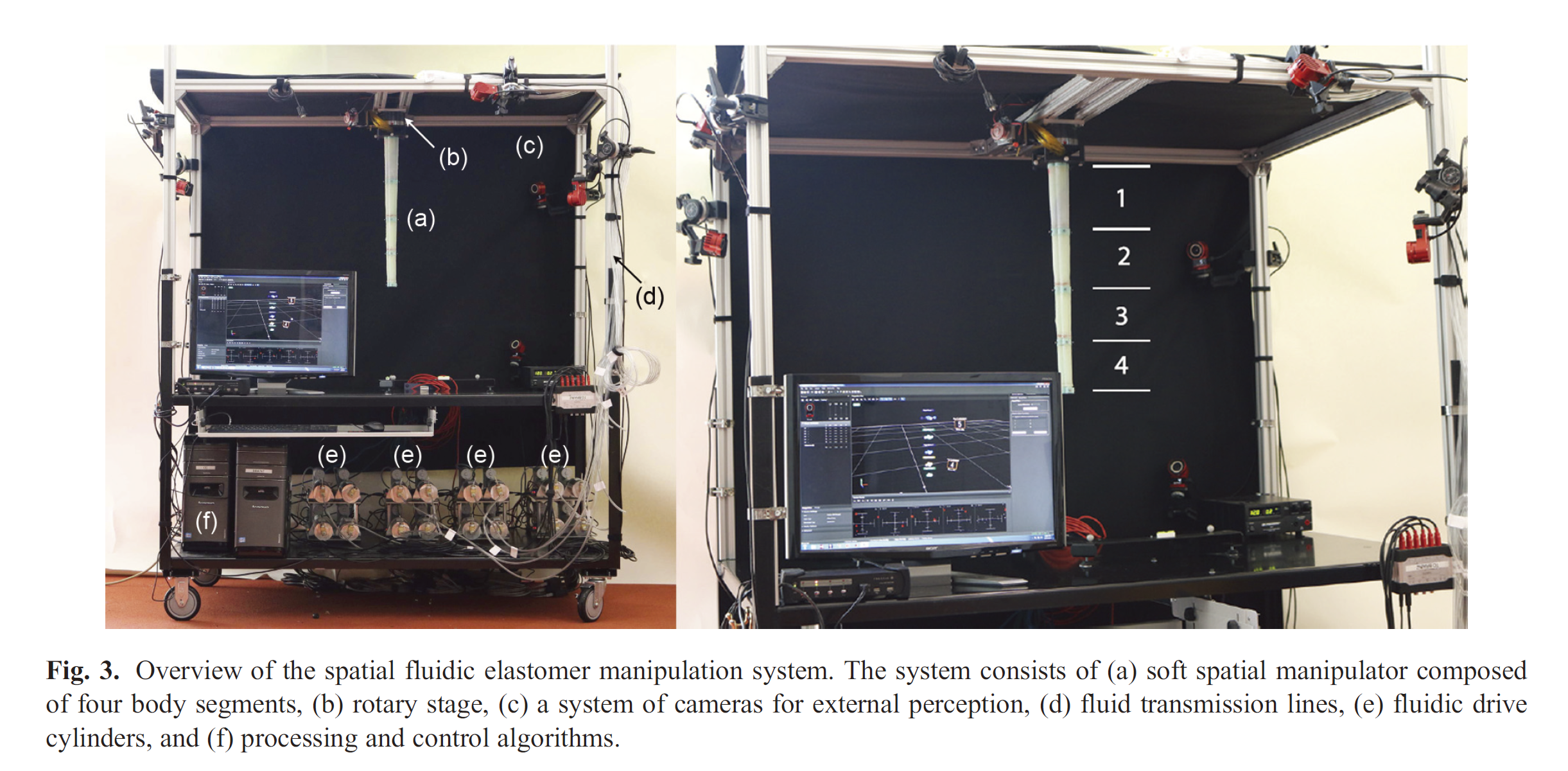
Subsystems: actuation, perception, power and computation
Actuation
Soft manipulator design
- Composed entirely from low durometer silicone rubbers
- Actuated by pressurizing fluid channels embedded within the arm.
Morphology:
- Modular in both design and fabrication
- Each module has four distributed fluidic actuators allowing it to move in three spatial dimensions.
- Hollow cylindrical interior accommodates fluid transmission lines and allows modular assembly.
- Soft segment endplates contain markers allowing an external camera system to localize their positions.
- A longitudinally tapered and clover-shaped exterior.
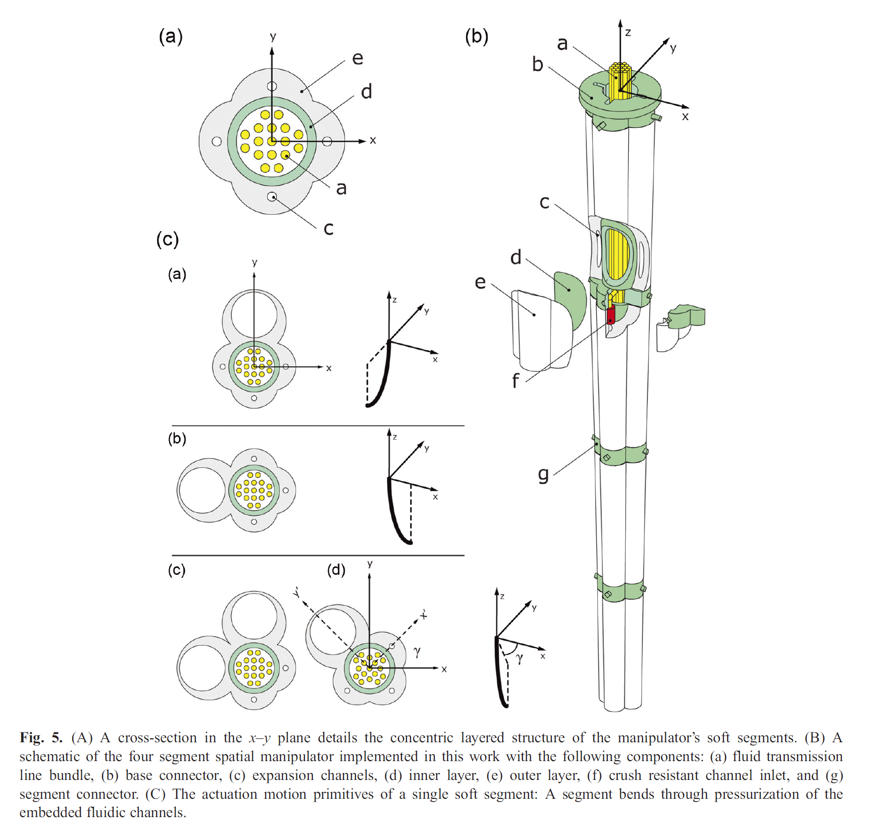
Bending motion primitives:
Combining actuation in the x and y directions allows for bending in any direction with zero rotation around the longitudinal axis.
Kinematic modeling
PCC-based kinematic model
Segment deformation
This simplified deformation model suggests that a significant portion of the actuator will deform under approximately constant curvature.
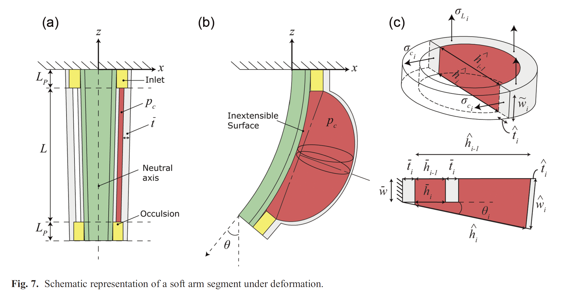
Consider the case of one of the segment’s channels deforming under pressure.
- Divide the channel in
- Iteratively apply the model each time increasing
Stresses and strains
Approximate the circumferential stress
When
Similarly, the longitudinal stress
Free parameter:
Circumferential and longitudinal strain
Updating channel geometry
Express the elongated wall
The accumulated angle
Conditions for constant curvature
Only the actuated region of the segment, i.e. the channel with arc length
Segment transformation
Transformation from the base of a segment to the tip
The kinematics of a multi-segment soft arm composed of N segments can be represented by cascading single segment transformations together:
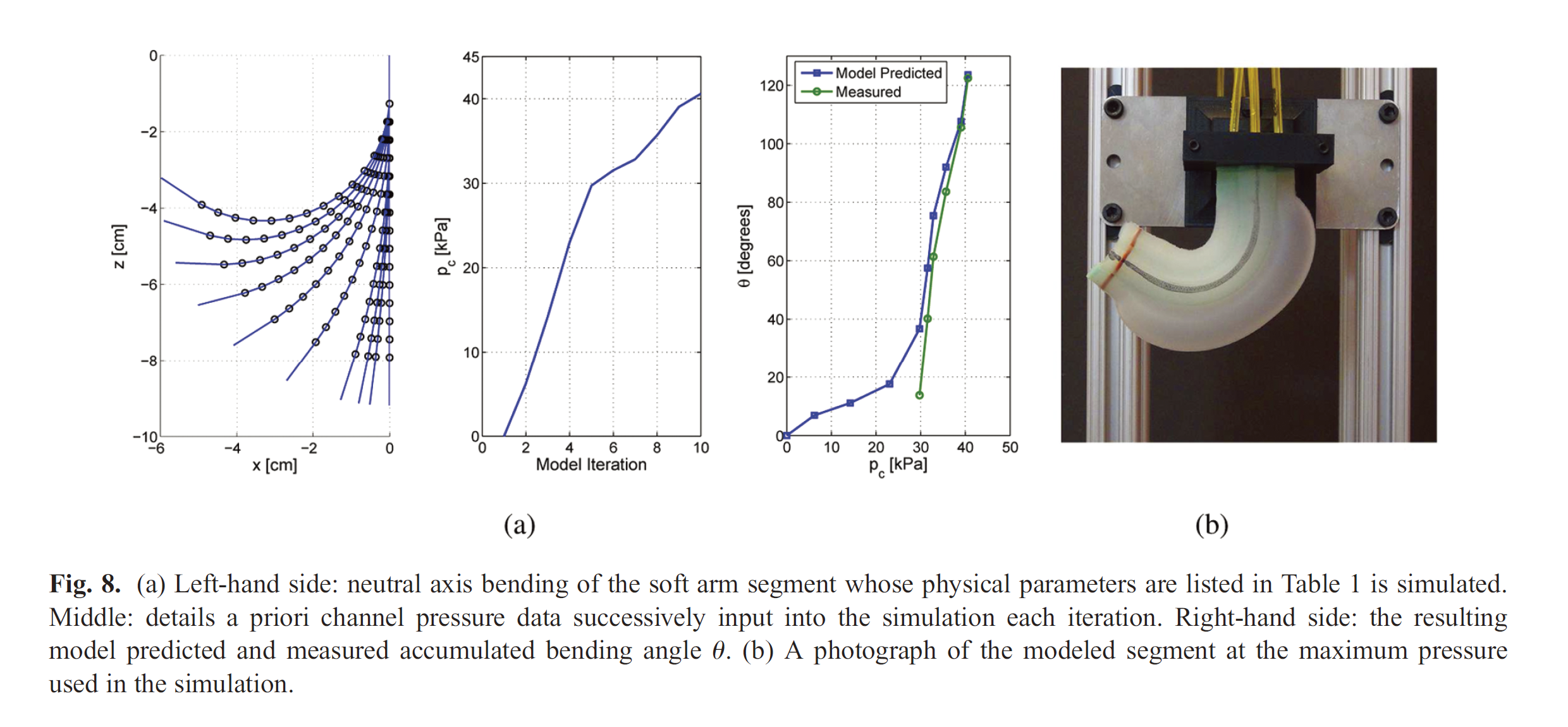
Model evaluations
Compare bending angle
Limitations
- Deviate at lower pressures
- Not directly establish the validity of the PCC-based model’s ability to describe the backbone’s continuous deformation
- Physical limitations. (maximum achievable bend angle of a segment)
- Force output limitation.(When the rubber is subject to high rates of strain, the material exhibits increased stiffness and more effectively transfers input fluid energy into actuator tip force. Then, when the load is constant, the elastomer exhibits a decrease in stiffness and accordingly the actuator’s channel expands under the fluid energy lessening the actuator’s tip force)
Manipulator fabrication
Fabricate the arm through a casting process that uses pourable silicone rubber and 3D printed molds.
Fabrication process:
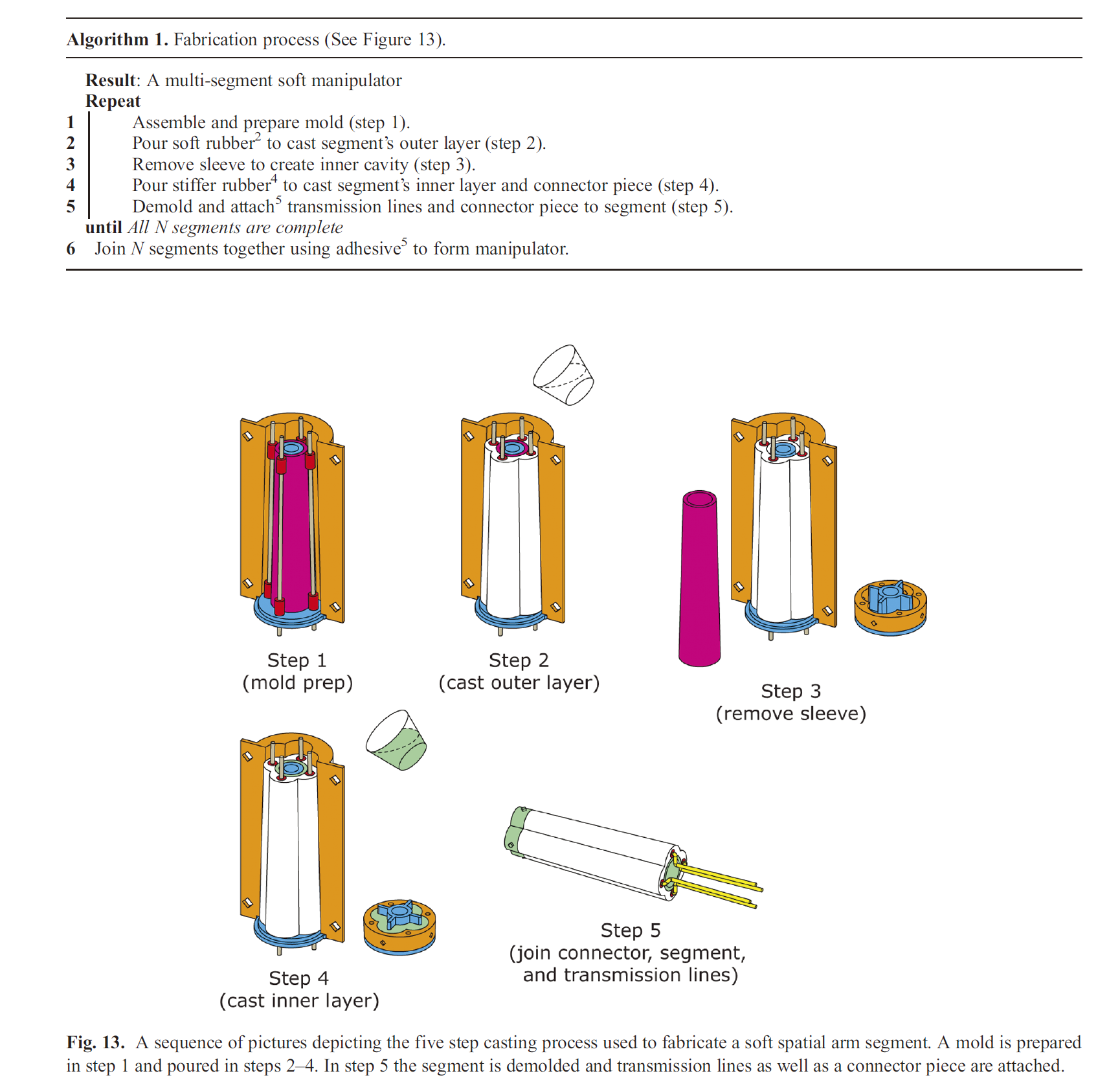
The mold consists of four parts:
- two-part outer shell (orange)
- interior piece (blue)
- metal rods (grey)
- removable sleeve (fuchsia)
All inlet pieces are cut to length and cleaned with rubbing alcohol to ensure good bond between their surface and the silicone rubber
Power
Pressurized fluids (air because of its low viscosity)
Challenges:
- need to supply each actuator with a continuous source of fluid energy for prolonged operation
- need the ability to continuously adjust input energy for smooth curvature control
Fluidic drive cylinders
Processing and control
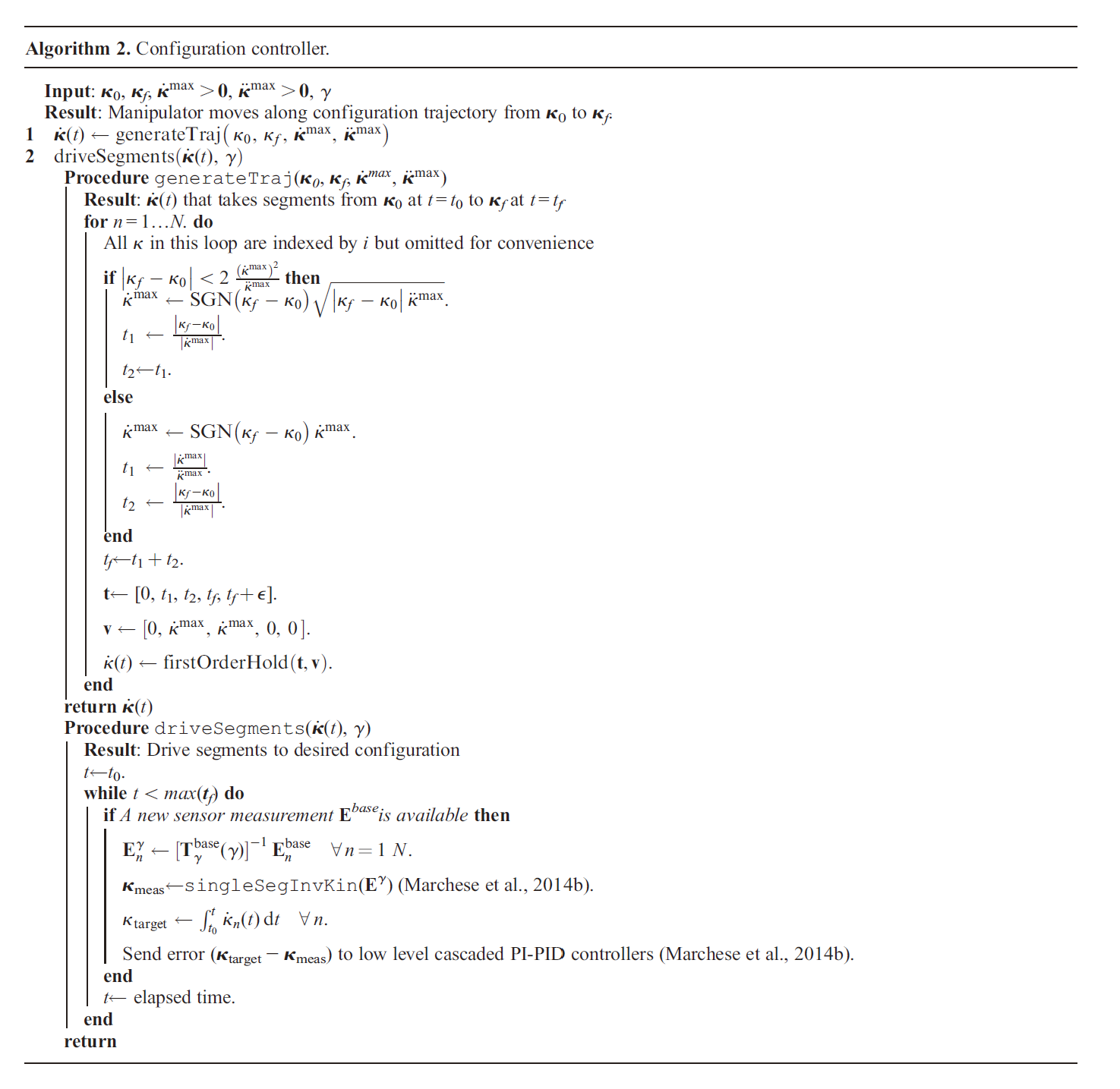
generateTraj()generates a realizable curvature velocity trajectorydriveSegments()advances the arm segments along the aforementioned trajectory under closed-loop control.- New measurement of segment endpoints in reference to a base frame.
- Transform into the sagittal plane specified by the rotation
- Use the endpoints to determine the measured curvature configuration representation
singleSegInvKin()) - Compute a reference configuration
- Input the computed error
Capabilities
Confined environment
The minimum confining space for a continuum manipulator segment can be significantly smaller than a rigid manipulator link in environments whose boundaries can be parameterized by curved cylinders or tubes.
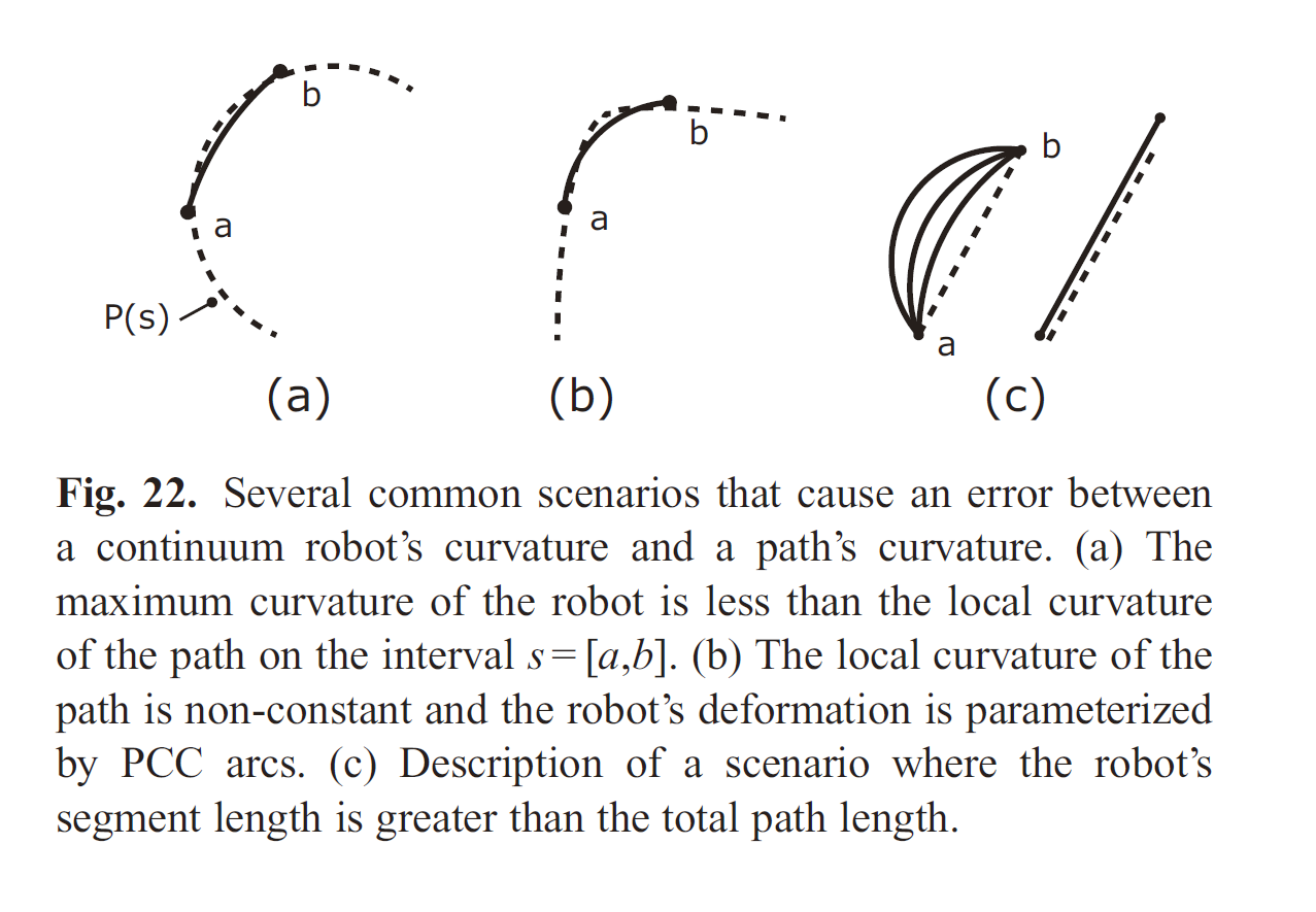
Shape fitting
In an environment where a collision-free path is parameterized by a curved shape, a continuum manipulator can generally fit the curvature of the path better than a rigid link manipulator with discrete joints.
Scenarios that cause an error between the continuum robot’s curvature and the path’s curvature:
Shape fitting algorithm
Objective: to incrementally advance a soft continuum manipulator along a curved path.
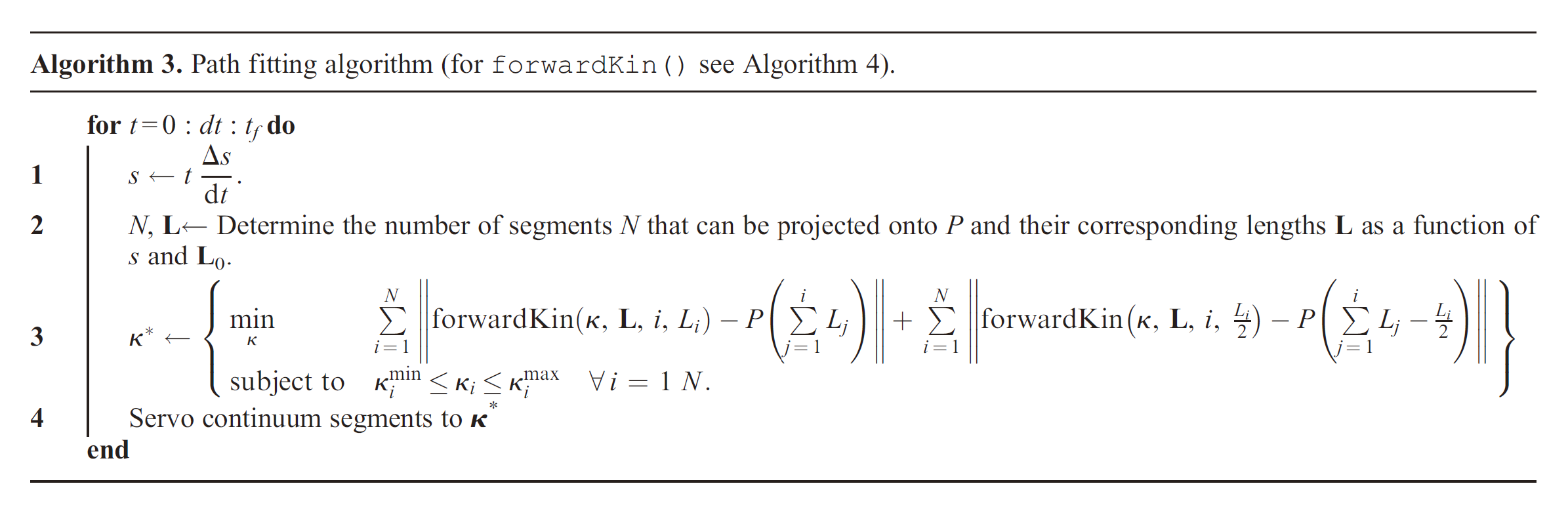
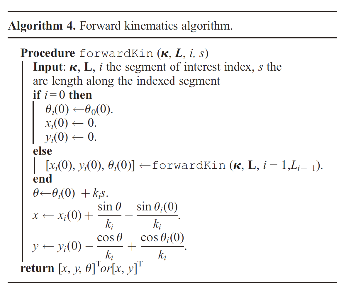
For each segment on the path, two points along the segment’s neutral axis, the mid and endpoint, are fit to the path by choosing the segment’s curvature
Forward kinematics procedure forwardKin(): recursively determining a point on the arm located a distance
Positioning
Inverse kinematics problem: a constrained nonlinear optimization
- Calculate
- Use the procedures in Algorithm 2 to plan and execute a curvature trajectory
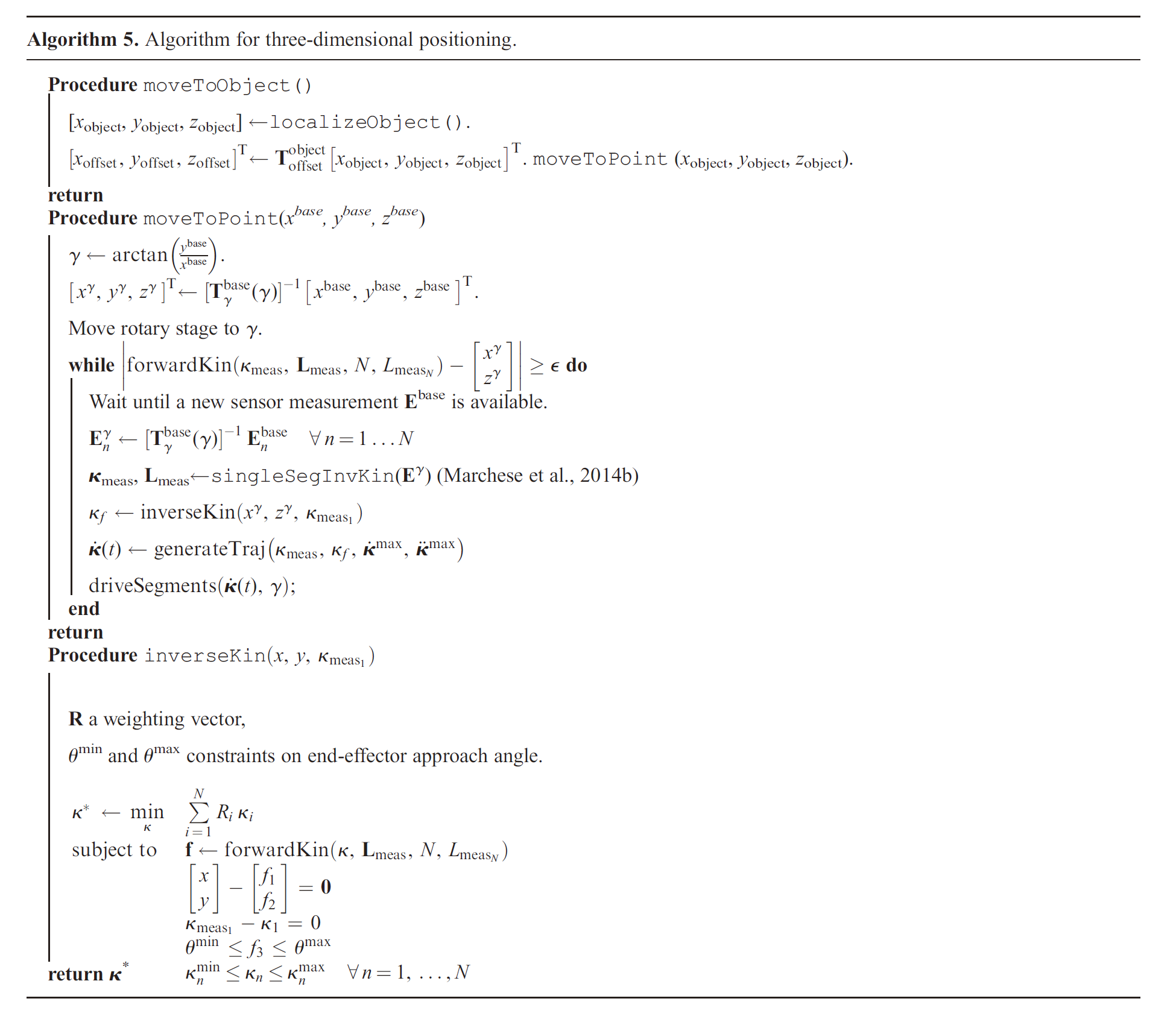
Positioning algorithm
moveToObject()
- Localize an object’s center in
localizeObject()) - Translate into a predetermined offset
moveToPoint(): strategy for moving the arm
- Rotate the arm into a sagittal plane defined by
- Iterative search for manipulator configuration
singleSegInvKin()uniquely fits a PCC model to the data
inverseKin(): determine the trajectory’s end configuration
Comments powered by Disqus.